This diagnostic mode works on my 1994 C280. It should work on 1994-1997 models, but I can't guarantee it.
The unit will connect to the underhood 38 pin diagnostic connector. When activated, the LED will flash a number of times which will correllate to a trouble code. Here are the parts needed to build your own tester. You also need a soldering iron if you want any of the components to stay put.
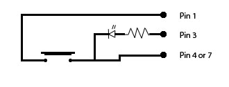
Here is a schematic of how the unit will be wired:
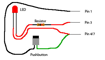
Here is a more visual diagram to the connections. Note, the long leg of the LED is the positive lead.
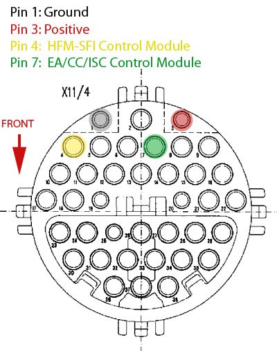
Finally, here is a view of the diagnostic connector with labeled pins
| DTC | Possible Cause |
| 1 | No Malfunction in system |
| 2 | Engine Coolant Temperature Sensor: Short Circuit Engine Coolant Temperature Sensor: Open Circuit Engine Coolant Temperature Sensor: Implausible Reading Engine Coolant Temperature Sensor: Intermittent Contact |
| 3 | Intake Air Temperature Sensor: Short Circuit Intake Air Temperature Sensor: Open Circuit Intake Air Temperature Sensor: Intermittent Contact |
| 4 | Mass Air Flow Meter: Air Flow Implausibly High Mass Air Flow Meter: Open Circuit |
| 5 | Throttle Position Switch: Throttle Valve Angle Implausibly High Throttle Position Switch: Air Flow Implausibly High Throttle Position Switch: Intermittent Contact |
| 8 | Idle Speed Control System: Lower Control Stop Idle Speed Control System: Upper Control Stop Cruise Controller or Electronic Throttle Actuator in "Limp-Home" Mode |
| 9 | Oxygen Sensor 1 (Before Catalytic Converter): Sensor Voltage Too High Oxygen Sensor 1 (Before Catalytic Converter): Cold or Open Circuit Oxygen Sensor 1 (Before Catalytic Converter): Sensor Voltage Implausible |
| 10 | Oxygen Sensor 2 (After Catalytic Converter): Sensor Voltage Too High Oxygen Sensor 2 (After Catalytic Converter): Cold or Open Circuit Oxygen Sensor 2 (After Catalytic Converter): Sensor Voltage Implausible |
| 11 | Oxygen Sensor 1 Heater(Before Catalytic Converter): Current too High Oxygen Sensor 1 Heater (Before Catalytic Converter): Current too Low Oxygen Sensor 1 Heater (Before Catalytic Converter): Short Circuit |
| 12 | Oxygen Sensor 2 Heater (After Catalytic Converter): Current too High Oxygen Sensor 2 Heater(After Catalytic Converter): Current too Low Oxygen Sensor 2 Heater (After Catalytic Converter): Short Circuit |
| 13 | Oxygen Sensor System: Operating at Rich Limit, Mixture Too Lean Oxygen Sensor System: Operating at Lean Limit, Mixture Too Rich |
| 14 | Injector Cylinder 1: Short Circuit to Positive Injector Cylinder 1: Open/Short Circuit to Ground |
| 15 | Injector Cylinder 2: Short Circuit to Positive Injector Cylinder 2: Open/Short Circuit to Ground |
| 16 | Injector Cylinder 3: Short Circuit to Positive Injector Cylinder 3: Open/Short Circuit to Ground |
| 17 | Injector Cylinder 4: Short Circuit to Positive Injector Cylinder 4: Open/Short Circuit to Ground |
| 18 | Injector Cylinder 5: Short Circuit to Positive Injector Cylinder 5: Open/Short Circuit to Ground |
| 19 | Injector Cylinder 6: Short Circuit to Positive Injector Cylinder 6: Open/Short Circuit to Ground |
| 20 | Adaptation at Idle: Too Rich Adaptation at Idle: Too Lean Adaptation at Lower Partial Load: Too Rich Adaptation at Lower Partial Load: Too Lean Adaptation at Upper Partial Load: Too Rich Adaptation at Upper Partial Load: Too Lean |
| 21 | Ignition Output 3 or Ignition Coil 3 for Cylinder 1: Misfire Ignition Output 3 or Ignition Coil 3 for Cylinder 6: Misfire Ignition Output 3 or Ignition Coil 3: Current Value Not Obtained |
| 22 | Ignition Output 1 or Ignition Coil 1 for Cylinder 2: Misfire Ignition Output 1 or Ignition Coil 1 for Cylinder 5: Misfire Ignition Output 1 or Ignition Coil 1: Current Value Not Obtained |
| 23 | Ignition Output 2 or Ignition Coil 2 for Cylinder 3: Misfire Ignition Output 2 or Ignition Coil 2 for Cylinder 4: Misfire Ignition Output 2 or Ignition Coil 2: Current Value Not Obtained |
| 24 | Crankshaft Position Sensor: Signal Not Recognized/Implausible Crankshaft Position Sensor: Magnet is Missing (segment control) Crankshaft Position Sensor: Number of Teeh Implausible (increment control) Crankshaft Position Sensor: RPM Implausibly High |
| 25 | Camshaft Position Sensor: Signal Not Recognized/Implausible (segment control) Camshaft Hall-effect Sensor: Signal Not Recognized/Implausible (increment control) |
| 27 | RPM Signal Output: Short Circuit to Ground RPM Signal Output: Short Circuit to Positive |
| 28 | Vehicle Speed Sensor: Signal Not Recognized Vehicle Speed Sensor: Signal Implausibly High |
| 30 | Fuel Pump Relay Module: Open/Short Circuit |
| 32 | Knock Sensor 1: Open Circuit Knock Sensor 2: Open Circuit |
| 33 | Maximum retard setting on at least one cylinder has been reached. Ignition angle deviation between the individual cylinders is > 6° crankshaft angle. |
| 34 | Knock Control Evaluation Circuit in Engine Control Module: Defective |
| 35 | AIR Pump Switchover Valve and/or AIR relay module: Open/Short Circuit |
| 36 | Purge Control Valve: Open/Short Circuit Purge Control Valve: Short Circuit to Positive |
| 37 | Upshift Delay Switchover Valve: Open/Short Circuit |
| 38 | Adjustable Camshaft Timing Solenoid: Short Circuit to Positive Adjustable Camshaft Timing Solenoid: Open/Short Circuit to Ground |
| 39 | EGR Switchover Valve: Short Circuit to Positive EGR Switchover Valve: Open/Short Circuit to Ground |
| 40 | Transmission Overload Protection Switch: Short Circuit to Ground Transmission Overload Protection Switch: Closed and 2nd Gear Recognized Transmission Overload Protection Switch: Open and 2nd Gear Recognized Transmission Overload Protection Switch: Implausible |
| 41 | CAN Communication from Engine Control Module: Defective |
| 42 | CAN Communication from ASR Control Module: Defective CAN Communication from EA/CC/ISC Control Module or CC/ISC Control Module: Defective CAN Communication from Diagnostive Module (OBD-II): Defective |
| 43 | Starter Signal Not Present |
| 45 | Fuel Safety Shut-Off of Electronic Accelerator or Cruise Control: Active |
| 46 | Resonance Intake Manifold Switchover Valve: Short Circuit to Positive Resonance Intake Manifold Switchover Valve: Open/Short Circuit to Ground |
| 48 | Oxygen Sensor 2 (After Catalytic Converter) Heater Relay Module: Short Circuit to Positive Oxygen Sensor 2 (After Catalytic Converter) Heater Relay Module: Open/Short Circuit to Ground |
| 49 | Voltage Supply Circuit at Engine Control Module: Implausible Voltage Supply Circuit at Engine Control Module: Low Voltage |
| 49 | Engine Control Module |
| DTC | Possible Cause |
| 1 | No Malfunction in system |
| 2 | CC/ISC Control Module Closed Throttle Position Switch Stop Lamp Switch Cruise Control Switch (OFF) Actual Value Potentiometer Starter Lock-Out/Backup Lamp Switch Engine Speed Signal Vehicle Speed Signal Safety Relay Within CC/ISC Control Module Engine Wiring Harness |
| 3 | CC/ISC Actuator Throttle Valve Actual Value Potentiometer Drive Actual Value Potentiometer Safety Contact Switch Closed Throttle Position Switch Recognition Potentiometer Voltage Supply Reset Not Accomplished (Actuator Adaptation) |
| 4 | Cruise Control Switch |
| 5 | Stop Lamp Switch |
| 7 | CAN Databus: Message from CC/ISC Control Module: Faulty Reception from Engine Control Module: Faulty |
| 8 | Left Front Axle Vehicle Speed Sensor from ABS or ETS/SPS Control Module |
| 9 | Rear Axle Vehicle Speed Sensor from ABS Control Module Left Rear Axle Vehicle Speed Sensor from ETS/SPS Control Module Incorrect CC/ISC Control Module Installed ETS Signal |
| 10 | Engine Speed Signal from Engine Control Module |
| 11 | Fuel Safety Shut-Off Signal to Engine Control Module |
| DTC | Possible Cause |
| 1 | No Malfunction in system |
| 2 | EA/CC/ISC Control Module Safety Contact Switch Stop Lamp Switch Cruise Control Switch (OFF) Actual Value Potentiometer Starter Lock-Out/Backup Lamp Switch Closed Throttle Position Switch Engine Speed Signal Vehicle Speed Signal Safety Relay Within CC/ISC Control Module Engine Wiring Harness |
| 3 | EA/CC/ISC Actuator Reference Potentiometer (Voltage Supply) Reference Potentiometer Actual Value Potentiometer Safety Contact Switch Closed Throttle Position Switch Actuator Motor Magnetic Clutch Reset Not Accomplished (Actuator Adaptation) |
| 4 | Cruise Control Switch |
| 5 | Stop Lamp Switch |
| 6 | Starter Lock-Out/Backup Lamp Switch |
| 7 | CAN Databus: Message from EA/CC/ISC Control Module: Faulty Reception from Engine Control Module: Faulty |
| 8 | Left Front Axle Vehicle Speed Sensor from ASR Control Module |
| 9 | Left Rear Axle Vehicle Speed Sensor from ASR Control Module |
| 10 | Engine Speed Signal from Engine Control Module |
| 11 | Fuel Safety Shut-Off Signal to Engine Control Module Closed Throttle Recognition Signal to Engine Control Module |
| 14 | Closed Throttle Position |
| 15 | CAN Databus: Data exchange with ASR control module implausible |